QCQI – Chapter 6 Detailed Summary: Quantum Fourier Transform & Applications
Learning Objectives
Define the discrete Fourier transform (DFT) and the quantum Fourier transform (QFT) on .
Derive the QFT circuit using and controlled phase rotations, including the bit-reversal.
Understand approximate QFT (aQFT): angle cutoff, error bounds, and asymptotic gate count.
Apply QFT to periodic states and phase kickback; connect to order-finding and phase estimation.
Implement the semiclassical inverse QFT (Griffiths–Niu) with adaptive single-qubit rotations.
From DFT to QFT
Classical DFT on points uses :
The QFT is the unitary implementing on the computational basis and linearly extending to superpositions.
Eureka! The QFT is just a change of basis from computational states to “phase states” .
Binary Expansion & Circuit Construction
Write in binary as and as . Using the binary fraction , the QFT factorizes:
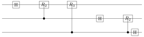
This yields a circuit with, for each qubit (from MSB to LSB): a Hadamard and controlled- rotations from lower-order bits, where . A final bit-reversal (sequence of SWAPs) restores natural order.
Eureka! Each qubit picks up a fractional phase from less significant bits via controlled rotations. The final state is a product state in the phase basis.
Complexity and Approximation
The exact circuit uses controlled rotations gates. For the approximate QFT (aQFT), drop with (small angles). For , the operator-norm error is and the gate count drops to .
Eureka! Tiny phase rotations contribute little: trimming them yields near-exact transforms with exponentially small error.
Phase Kickback
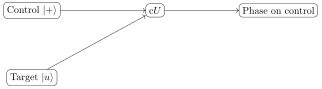
If , then a controlled- from a control qubit in kicks the eigenphase to the control:
Applying an inverse QFT to a register of such phase-kicked qubits reveals binary digits of (core of phase estimation).
Eureka! Controlled unitaries turn global eigenphases into observable relative phases on controls.
Periodic States & Fourier Sampling
Given a state uniform on a period- coset,
the QFT produces peaks near integer multiples of . Sampling yields and hence information about via continued fractions.
Eureka! QFT converts periodicity in -space into spikes in -space.
Semiclassical Inverse QFT (Griffiths–Niu)
Measure qubits one-by-one from least significant to most, feed forward classically controlled rotations to cancel known phases before each , and continue. This replaces multi-qubit entangling rotations with adaptive single-qubit gates and measurements.
Eureka! Measurement + classical feed-forward can substitute for many entangling gates in .
Worked Nuggets
3-qubit QFT. on MSB; apply from middle, from LSB; repeat pattern for remaining qubits; final SWAP.
aQFT error. Dropping all rotations with angle incurs operator-norm error (coarse bound).
Fourier adder (idea). Addition by phases: QFT phase rotations encoding addend inverse QFT.
Pseudo-code Aids
Pseudocode — QFT on qubits (exact)
Input: qubits ordered MSB..LSB for from 0 to : apply to qubit for to : apply controlled- with control target finally: reverse bit order using SWAPs
Pseudocode — Approximate QFT (angle cutoff )
Input: , cutoff for each controlled- in QFT: if , omit it Gate count , operator error
Pseudocode — Semiclassical (LSB-first)
Input: -qubit register for from down to 0: apply depending on previously measured bits apply ; measure qubit ; update phases
Schematics
3-Qubit QFT (concept)

Phase Kickback

Hands-on Notebook (Multi-Backend)
Run: L08
In the first cell set backend to one of: cirq, pennylane, braket, pyquil, or qiskit.
Mini-Lab Ideas
Verify QFT on basis states: compare statevector phases to analytic DFT.
Implement aQFT with various ; plot fidelity vs. gate count.
Prepare a period- state and recover from QFT samples using continued fractions.